|
Critical: S.M.A.R.T. failure and errors mean the drive is at risk. |
Introduction
S.M.A.R.T. (Self-Monitoring, Analysis and Reporting Technology) monitors and checks the health of a drive. It will detect and report if the drive has errors and is at risk of failure.
A drive that supports S.M.A.R.T may run a few tests or maintenance jobs to check for errors. The results are kept in the self-test log of the drive. More detail on the health of the drive can be seen by looking at the S.M.A.R.T. Attributes. Drives have pre-set values that should not be exceeded under normal conditions.
Drive Self-Tests
A drive that support S.M.A.R.T may offer self-tests.
- Short (Quick) Test
Takes a few moments to complete.
Checks the electrical and mechanical read/write state of the drive.
It will also scan some of the media for errors. (The scan area is vendor-specific with a time limit for the test). - Extended (Long) Test
Takes much longer to complete.
A longer and more thorough version of the short test.
Drive Check Tools
Western Digital drives support S.M.A.R.T. version III.
A test should be done on drives that have errors.
Need more help?
Answer ID 12452: Steps to Check Drives for Errors or Failures on Windows and macOS
 | Older versions of S.M.A.R.T. in the BIOS may cause problems while scanning the drive. |
- Windows
- macOS
- Western Digital Software
Western Digital S.M.A.R.T Attributes
Each drive manufacturer defines a set of attributes and thresholds that should not be passed under normal operation. Each attribute has a raw value. The meaning of the value is set by the vendor.
An attribute is correct when the value is greater than or equal to the one set.
This is not true for a critical attribute or predictive failure. The drive is considered bad and should be replaced.
An attribute with a threshold of 0 is not able to predict failure because the Value cannot be less than 0.
Attribute Fields
- Identifier: the meaning of the attribute.
- Data (Raw): raw value from a sensor orcounter. The data is checked by a vendor process.
- Threshold: the failure limit value of the attribute.
- Value: the current relative "health" of the attribute. This number is calculated by a process using the raw data.
- Worst: the worst (smallest) value ever found for the lifetime of the drive.
|
|
|
|
|
|---|---|---|---|
| 1830xB7 | SATA Downshift Error Count or Runtime Bad Block | Low | Western Digital attribute: Either the number of downshifts of link speed (e.g. from 6Gbit/s to 3Gbit/s) or the total number of data blocks with detected, uncorrectable errors encountered during normal operation. Although degradation of this parameter can be an indicator of drive aging and/or potential electromechanical problems, it does not directly indicate imminent drive failure. |
| 1850xB9 | Head Stability | Western Digital attribute | |
| 1860xBA | Induced Op-Vibration Detection | Western Digital attribute | |
| 1890xBD | High Fly Writes | Low | HDD manufacturers implement a flying height sensor that attempts to provide additional protections for write operations by detecting when a recording head is flying outside its normal operating range. If an unsafe fly height condition is encountered, the write process is stopped, and the information is rewritten or reallocated to a safe region of the hard drive. This attribute indicates the count of these errors detected over the lifetime of the drive.
This feature is implemented in most modern Seagate drives and some of Western Digital's drives, beginning with the WD Enterprise WDE18300 and WDE9180 Ultra2 SCSI hard drives, and will be included on all future WD Enterprise products |
| 1930xC1 | Load Cycle Count or Load/Unload Cycle Count | Low | Count of load/unload cycles into head landing zone position. Some drives use 225 (0xE1) for Load Cycle Count instead.
Western Digital rates their VelociRaptor drives for 600,000 load/unload cycles, and WD Green drives for 300,000 cycles;[the latter ones are designed to unload heads often to conserve power. On the other hand, the WD3000GLFS (a desktop drive) is specified for only 50,000 load/unload cycles. Some laptop drives and "green power" desktop drives are programmed to unload the heads whenever there has not been any activity for a short period, to save power. Operating systems often access the file system a few times a minute in the background,causing 100 or more load cycles per hour if the heads unload: the load cycle rating may be exceeded in less than a year.There are programs for most operating systems that disable the Advance Power Management (APM) and Automatic acoustic management (AAM) features causing frequent load cycles. |
Standard S.M.A.R.T Attributes - ATA
Standard Attributes are used on most drives and are not unique by vendor.
|
|
|
|
|
|---|---|---|---|
| 010x01 | Read Error Rate | Low | (Vendor specific raw value.) Stores data related to the rate of hardware read errors that occurred when reading data from a disk surface. The raw value has different structure for different vendors and is often not meaningful as a decimal number. For some drives, this number may increase during normal operation without necessarily signifying errors. |
| 020x02 | Throughput Performance | High | Overall (general) throughput performance of a hard disk drive. If the value of this attribute is decreasing there is a high probability that there is a problem with the disk. |
| 030x03 | Spin-Up Time | Low | Average time of spindle spin up (from zero RPM to fully operational [milliseconds]). |
| 040x04 | Start/Stop Count | A tally of spindle start/stop cycles. The spindle turns on, and hence the count is increased, both when the hard disk is turned on after having before been turned entirely off (disconnected from power source) and when the hard disk returns from having previously been put to sleep mode. | |
| 050x05 | Reallocated Sectors Count | Low | Count of reallocated sectors. The raw value represents a count of the bad sectors that have been found and remapped.Thus, the higher the attribute value, the more sectors the drive has had to reallocate. This value is primarily used as a metric of the life expectancy of the drive; a drive which has had any reallocations at all is significantly more likely to fail in the immediate months. |
| 060x06 | Read Channel Margin | Margin of a channel while reading data. The function of this attribute is not specified. | |
| 070x07 | Seek Error Rate | Varies | (Vendor specific raw value.) Rate of seek errors of the magnetic heads. If there is a partial failure in the mechanical positioning system, then seek errors will arise. Such a failure may be due to numerous factors, such as damage to a servo, or thermal widening of the hard disk. The raw value has different structure for different vendors and is often not meaningful as a decimal number. For some drives, this number may increase during normal operation without necessarily signifying errors. |
| 080x08 | Seek Time Performance | High | Average performance of seek operations of the magnetic heads. If this attribute is decreasing, it is a sign of problems in the mechanical subsystem. |
| 090x09 | Power-On Hours | Count of hours in power-on state. The raw value of this attribute shows total count of hours (or minutes, or seconds, depending on manufacturer) in power-on state."By default, the total expected lifetime of a hard disk in perfect condition is defined as 5 years (running every day and night on all days). This is equal to 1825 days in 24/7 mode or 43800 hours."On some pre-2005 drives, this raw value may advance erratically and/or "wrap around" (reset to zero periodically). | |
| 100x0A | Spin Retry Count | Low | Count of retry of spin start attempts. This attribute stores a total count of the spin start attempts to reach the fully operational speed (under the condition that the first attempt was unsuccessful). An increase of this attribute value is a sign of problems in the hard disk mechanical subsystem. |
| 110x0B | Recalibration Retries or Calibration Retry Count | Low | This attribute indicates the count that recalibration was requested (under the condition that the first attempt was unsuccessful). An increase of this attribute value is a sign of problems in the hard disk mechanical subsystem. |
| 120x0C | Power Cycle Count | This attribute indicates the count of full hard disk power on/off cycles. | |
| 130x0D | Soft Read Error Rate | Low | Uncorrected read errors reported to the operating system. |
| 220x16 | Current Helium Level | High | Specific to He8 drives from HGST. This value measures the helium inside of the drive specific to this manufacturer. It is a pre-fail attribute that trips once the drive detects that the internal environment is out of specification |
| 1700xAA | Available Reserved Space | See attribute E8 | |
| 1710xAB | SSD Program Fail Count | The total number of flash program operation failures since the drive was deployed.[36] Identical to attribute 181. | |
| 1720xAC | SSD Erase Fail Count | Counts the number of flash erase failures. This attribute returns the total number of Flash erase operation failures since the drive was deployed. This attribute is identical to attribute 182. | |
| 1730xAD | SSD Wear Leveling Count | Counts the maximum worst erase count on any block. | |
| 1740xAE | Unexpected Power Loss Count | Also known as "Power-off Retract Count" per conventional HDD terminology. Raw value reports the number of unclean shutdowns, cumulative over the life of an SSD, where an "unclean shutdown" is the removal of power without STANDBY IMMEDIATE as the last command (regardless of PLI activity using capacitor power). Normalized value is always 100. | |
| 1750xAF | Power Loss Protection Failure | Last test result as microseconds to discharge cap, saturated at its maximum value. Also logs minutes since last test and lifetime number of tests. Raw value contains the following data:
|
|
| 1760xB0 | Erase Fail Count | S.M.A.R.T. parameter indicates a number of flash erase command failures. | |
| 1770xB1 | Wear Range Delta | Delta between most-worn and least-worn Flash blocks. It describes how good/bad the wearleveling of the SSD works on a more technical way. | |
| 1810xB5 | Program Fail Count Total or Non-4K Aligned Access Count | Low | Total number of Flash program operation failures since the drive was deployed.[40] Number of user data accesses (both reads and writes) where LBAs are not 4 KiB aligned (LBA % 8 != 0) or where size is not modulus 4 KiB (block count != 8), assuming logical block size (LBS) = 512 B |
| 1840xB8 | End-to-End error / IOEDC | Low | This attribute is a part of Hewlett-Packard's SMART IV technology, as well as part of other vendors' IO Error Detection and Correction schemas, and it contains a count of parity errors which occur in the data path to the media via the drive's cache RAM. |
| 1870xBB | Reported Uncorrectable Errors | Low | The count of errors that could not be recovered using hardware ECC |
| 1880xBC | Command Timeout | Low | The count of aborted operations due to HDD timeout. Normally this attribute value should be equal to zero. |
| 1900xBE | Temperature Difference or Airflow Temperature | Varies | Value is equal to (100-temp. °C), allowing manufacturer to set a minimum threshold which corresponds to a maximum temperature. This also follows the convention of 100 being a best-case value and lower values being undesirable. However, some older drives may instead report raw Temperature (identical to 0xC2) or Temperature minus 50 here. |
| 1910xBF | G-sense Error Rate | Low | The count of errors resulting from externally induced shock and vibration |
| 1920xC0 | Power-off Retract Count, Emergency Retract Cycle Count (Fujitsu),or Unsafe Shutdown Count | Low | Number of power-off or emergency retract cycles |
| 1940xC2 | Temperature or Temperature Celsius | Low | Indicates the device temperature, if the appropriate sensor is fitted. Lowest byte of the raw value contains the exact temperature value (Celsius degrees). |
| 1950xC3 | Hardware ECC Recovered | Varies | (Vendor-specific raw value.) The raw value has different structure for different vendors and is often not meaningful as a decimal number. For some drives, this number may increase during normal operation without necessarily signifying errors. |
| 1960xC4 | Reallocation Event Count | Low | Count of remap operations. The raw value of this attribute shows the total count of attempts to transfer data from reallocated sectors to a spare area. Both successful and unsuccessful attempts are counted. |
| 1970xC5 | Current Pending Sector Count | Low | Count of "unstable" sectors (waiting to be remapped, because of unrecoverable read errors). If an unstable sector is subsequently read successfully, the sector is remapped and this value is decreased. Read errors on a sector will not remap the sector immediately (since the correct value cannot be read and so the value to remap is not known, and also it might become readable later); instead, the drive firmware remembers that the sector needs to be remapped, and will remap it the next time it has been successfully read.
However, some drives will not immediately remap such sectors when successfully read; instead the drive will first attempt to write to the problem sector, and if the write operation is successful the sector will then be marked as good (in this case, the "Reallocation Event Count" (0xC4) will not be increased). This is a serious shortcoming, for if such a drive contains marginal sectors that consistently fail only after some time has passed following a successful write operation, then the drive will never remap these problem sectors. |
| 1980xC6 | (Offline) Uncorrectable Sector Count | Low | The total count of uncorrectable errors when reading/writing a sector. A rise in the value of this attribute indicates defects of the disk surface and/or problems in the mechanical subsystem |
| 1990xC7 | UltraDMA CRC Error Count | Low | The count of errors in data transfer via the interface cable as determined by ICRC (Interface Cyclic Redundancy Check). |
| 2000xC8 | Multi-Zone Error Rate | Low | The count of errors found when writing a sector. The higher the value, the worse the disk's mechanical condition is |
| 2000xC8 | Write Error Rate | Low | The total count of errors when writing a sector |
| 2010xC9 | Soft Read Error Rate or TA Counter Detected |
Low | Count indicates the number of uncorrectable software read errors. |
| 2020xCA | Data Address Mark errors or TA Counter Increased |
Low | Count of Data Address Mark errors (or vendor-specific) |
| 2030xCB | Run Out Cancel | Low | The number of errors caused by incorrect checksum during the error correction. |
| 2040xCC | Soft ECC Correction | Low | Count of errors corrected by the internal error correction software |
| 2050xCD | Thermal Asperity Rate | Low | Count of errors due to high temperature |
| 2060xCE | Flying Height | Height of heads above the disk surface. If too low, head crash is more likely; if too high, read/write errors are more likely | |
| 2070xCF | Spin High Current | Low | Amount of surge current used to spin up the drive |
| 2080xD0 | Spin Buzz | Count of buzz routines needed to spin up the drive due to insufficient power | |
| 2090xD1 | Offline Seek Performance | Drive's seek performance during its internal tests | |
| 2100xD2 | Vibration During Write | Found in Maxtor 6B200M0 200GB and Maxtor 2R015H1 15GB disks. | |
| 2110xD3 | Vibration During Write | A recording of a vibration encountered during write operations. | |
| 2120xD4 | Shock During Write | A recording of shock encountered during write operations. | |
| 2200xDC | Disk Shift | Low | Distance the disk has shifted relative to the spindle (usually due to shock or temperature). Unit of measure is unknown. |
| 2210xDD | G-Sense Error Rate | Low | The count of errors resulting from externally induced shock and vibration. More typically reported at 0xBF. |
| 2220xDE | Loaded Hours | Time spent operating under data load (movement of magnetic head armature) | |
| 2230xDF | Load/Unload Retry Count | Count of times head changes position. | |
| 2240xE0 | Load Friction | Low | Resistance caused by friction in mechanical parts while operating |
| 2250xE1 | Load/Unload Cycle Count | Low | Total count of load cycles. Some drives use 193 (0xC1) for Load Cycle Count instead. See Description for 193 for significance of this number |
| 2260xE2 | Load 'In'-time | Total time of loading on the magnetic heads actuator (time not spent in parking area). | |
| 2270xE3 | Torque Amplification Count | Low | Count of attempts to compensate for platter speed variations |
| 2280xE4 | Power-Off Retract Cycle | Low | The number of power-off cycles which are counted whenever there is a "retract event" and the heads are loaded off of the media such as when the machine is powered down, put to sleep, or is idle. |
| 2300xE6 | GMR Head Amplitude (magnetic HDDs), Drive Life Protection Status (SSDs) | Amplitude of "thrashing" (repetitive head moving motions between operations).
In solid-state drives, indicates whether usage trajectory is outpacing the expected life curve |
|
| 2310xE7 | Life Left (SSDs) or Temperature | Indicates the approximate SSD life left, in terms of program/erase cycles or available reserved blocks. A normalized value of 100 represents a new drive, with a threshold value at 10 indicating a need for replacement. A value of 0 may mean that the drive is operating in read-only mode to allow data recovery.
Previously (pre-2010) occasionally used for Drive Temperature (more typically reported at 0xC2). |
|
| 2320xE8 | Endurance Remaining or Available Reserved Space | Number of physical erase cycles completed on the SSD as a percentage of the maximum physical erase cycles the drive is designed to endure.
Intel SSDs report the available reserved space as a percentage of the initial reserved space. |
|
| 2330xE9 | Media Wearout Indicator (SSDs) or Power-On Hours | Intel SSDs report a normalized value from 100, a new drive, to a minimum of 1. It decreases while the NAND erase cycles increase from 0 to the maximum-rated cycles.
Previously (pre-2010) occasionally used for Power-On Hours (more typically reported in 0x09). |
|
| 2340xEA | Average erase count AND Maximum Erase Count | Decoded as: byte 0-1-2 = average erase count (big endian) and byte 3-4-5 = max erase count (big endian) | |
| 2350xEB | Good Block Count AND System(Free) Block Count | Decoded as: byte 0-1-2 = good block count (big endian) and byte 3-4 = system (free) block count. | |
| 2400xF0 | Head Flying Hours or 'Transfer Error Rate' | Time spent during the positioning of the drive heads. Some Fujitsu drives report the count of link resets during a data transfer | |
| 2410xF1 | Total LBAs Written | Total count of LBAs written. | |
| 2420xF2 | Total LBAs Read | Total count of LBAs read. Some S.M.A.R.T. utilities will report a negative number for the raw value since in reality it has 48 bits rather than 32. |
|
| 2430xF3 | Total LBAs Written Expanded | The upper 5 bytes of the 12-byte total number of LBAs written to the device. The lower 7 byte value is located at attribute 0xF1. | |
| 2440xF4 | Total LBAs Read Expanded | The upper 5 bytes of the 12-byte total number of LBAs read from the device. The lower 7 byte value is located at attribute 0xF2 | |
| 2490xF9 | NAND Writes (1GiB) | Total NAND Writes. Raw value reports the number of writes to NAND in 1 GB increments | |
| 2500xFA | Read Error Retry Rate | Low | Count of errors while reading from a disk |
| 2510xFB | Minimum Spares Remaining | The Minimum Spares Remaining attribute indicates the number of remaining spare blocks as a percentage of the total number of spare blocks available. | |
| 2520xFC | Newly Added Bad Flash Block | The Newly Added Bad Flash Block attribute indicates the total number of bad flash blocks the drive detected since it was first initialized in manufacturing. | |
| 2540xFE | Free Fall Protection | Low | Count of "Free Fall Events" detected |
Standard S.M.A.R.T Attributes - NVMe
NVMe specification has defined unified S.M.A.R.T. attributes for different drive manufacturers.
|
|
|
|
|
|---|---|---|---|
| 00x00 | 1 | Critical Warning | Critical warnings for the state of the controller. Bit definition: Bit 00, value 1: Available spare is below threshold. Bit 01, value 1: Temperature is over threshold. Bit 02, value 1: Drive reliability is degraded. Bit 03, value 1: Drive is in read only mode. |
| 10x01 | 2 | Composite Temperature | Temperature in kelvins representing the current composite temperature of the controller and its namespace(s). |
| 30x03 | 1 | Available Spare | Percentage of available spare. |
| 40x04 | 1 | Available Spare Threshold | Percentage of available spare threshold. |
| 50x05 | 1 | Percentage Used | Percentage of drive life used. |
| 70x07 | 25 | Reserved | - |
| 320x20 | 16 | Data Units Read | Number of 512-byte data units the host has read from the controller. This value does not include metadata. This value is reported in thousands (i.e., a value of 1 corresponds to 1000 units of 512 bytes written) and is rounded up. |
| 480x30 | 16 | Data Units Written | Number of 512-byte data units the host has written to the controller. This value does not include metadata. This value is reported in thousands (i.e., a value of 1 corresponds to 1000 units of 512 bytes written) and is rounded up. |
| 640x40 | 16 | Host Read Commands | Number of read commands completed by the controller. |
| 800x50 | 16 | Host Write Commands | Number of write commands completed by the controller. |
| 960x60 | 16 | Controller Busy Time | Amount of time the controller is busy with I/O commands. |
| 1120x70 | 16 | Power Cycles | Number of power cycles. |
| 1280x80 | 16 | Power On Hours | Number of power-on hours, excluding time powered on in non-operational power state. |
| 1440x90 | 16 | Unsafe Shutdowns | Number of unsafe shutdowns. Incremented when a Shutdown Notification is not received prior to loss of power. |
| 1600xA0 | 16 | Media Errors | Number of occurrences where the controller detected an unrecovered data integrity error, including uncorrectable ECC, CRC checksum failure, or LBA tag mismatch. |
| 1760xB0 | 16 | Number of Error Information Log Entries | Number of Error Information log entries over the life of the controller. |
| 1920xC0 | 4 | Number of Error Information Log Entries | Number of Error Information log entries over the life of the controller. |
| 1760xB0 | 16 | Warning Composite Temperature Time | - |
| 1960xC4 | 4 | Critical Composite Temperature Time | - |
| 2000xC8 | 2×8 | Temperature Sensor 1-8 |
- |
| 2160xD8 | 4×2 | Thermal Management Temperature 1/2 Transition Count | - |
| 2240xE0 | 4×2 | Total Time For Thermal Management Temperature 1/2 | - |
| 2320xE8 | 280 | Reserved | - |
Examples of S.M.A.R.T Failures
IMPORTANT:
- External SSD drives that connect using USB interface does not support S.M.A.R.T parameters.
Running S.M.A.R.T on an External SSD connected using USB a interface will result in a failure message. - External SSD drives that use the USB interface do not support S.M.A.R.T parameters. The test will fail.
- Drives that result is S.M.A.R.T errors or failures should not be used for data storage.
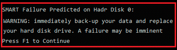
S.M.A.R.T. Failure - Computer BIOS level
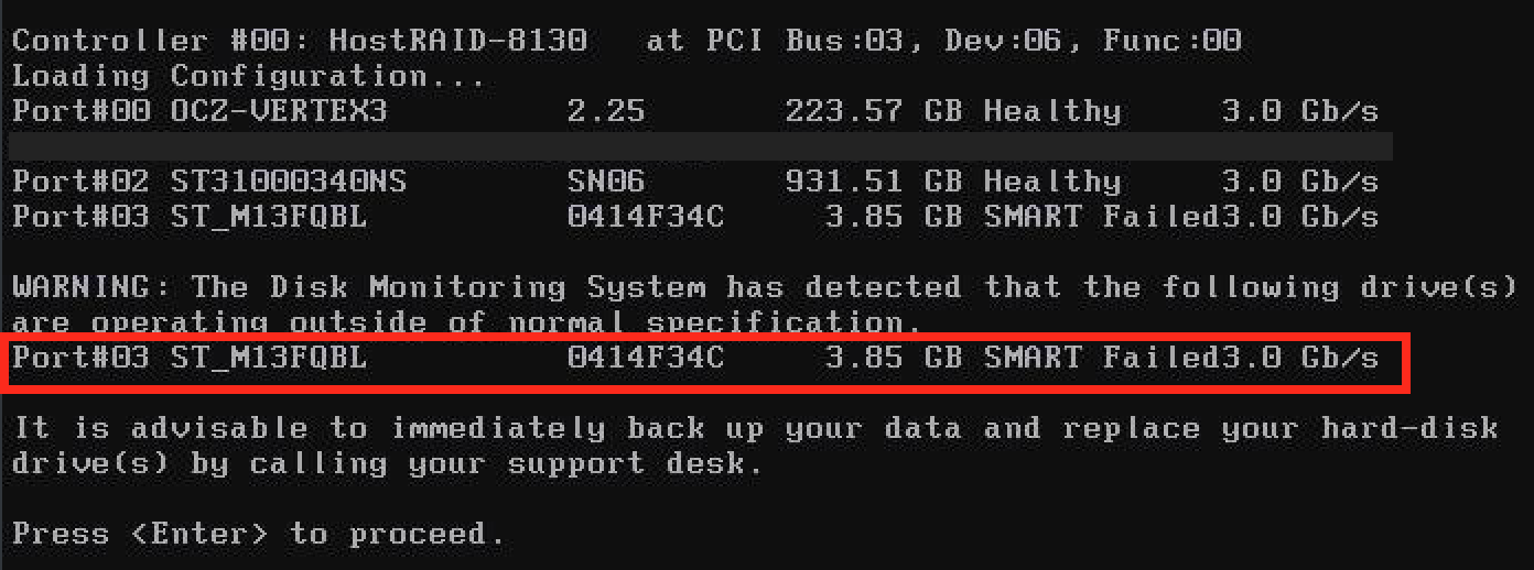
S.M.A.R.T. Failure - Server BIOS level

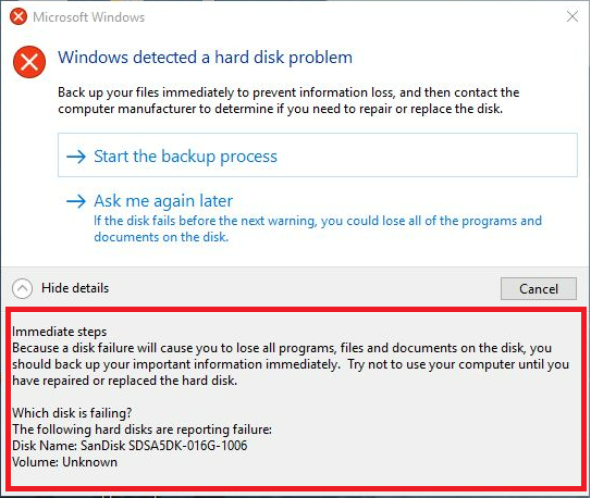
S.M.A.R.T. Failure - Windows Operating System level
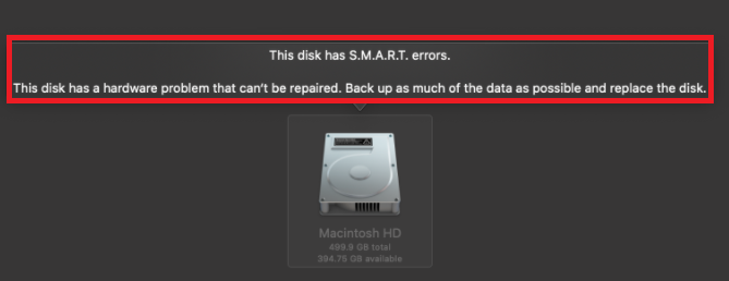
S.M.A.R.T. Failure - macOS System level